Consider The System Of Capacitors Shown In The Figure Below
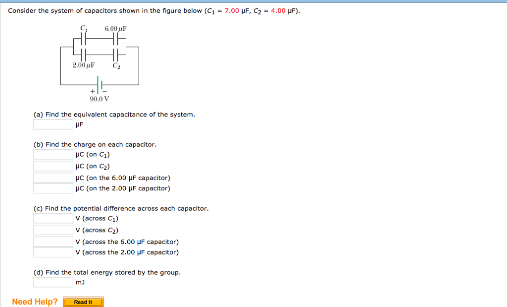
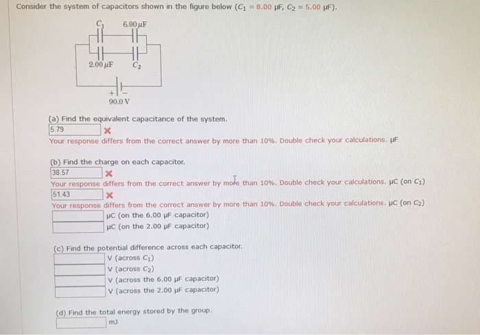
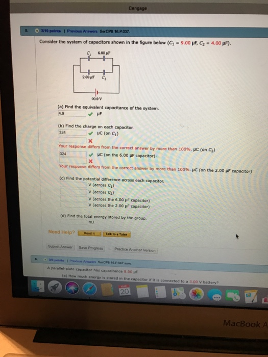
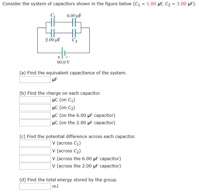
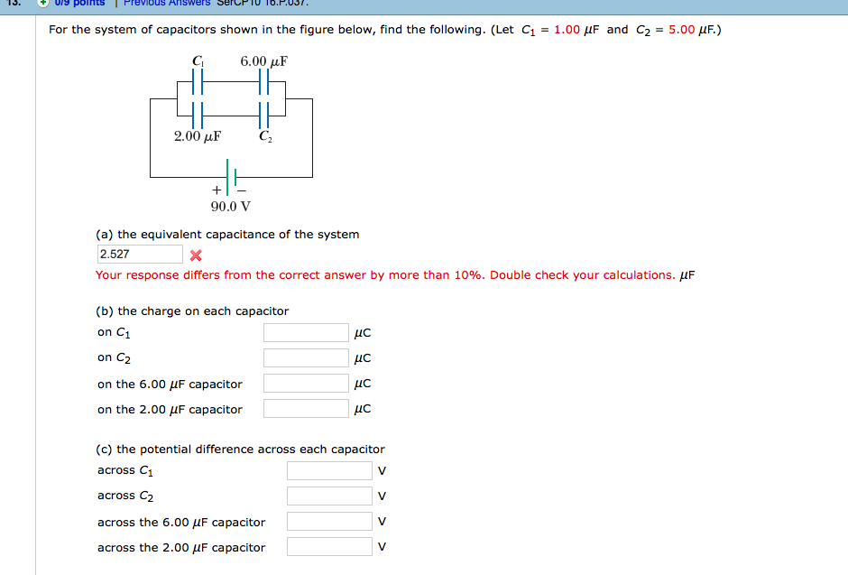
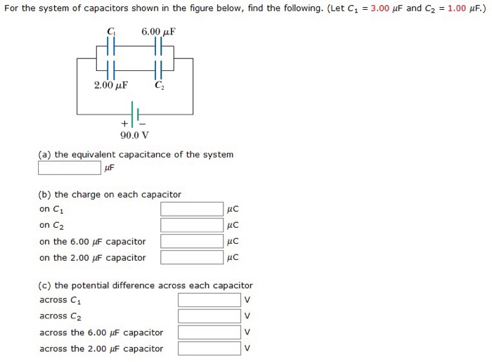
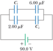
Consider the system of capacitors shown in the figure below. For the system of capacitors shown in the the figure below Figure 1 a potential difference of 250 V is maintained across a b. How much charge does the 650 nF capacitor store in nC. For the system of capacitors shown in the figure below find the following.
Your submitted answer was incorrect. Let C1 1260 µF. The voltage across a 4-LF capacitor is shown in the given figure.
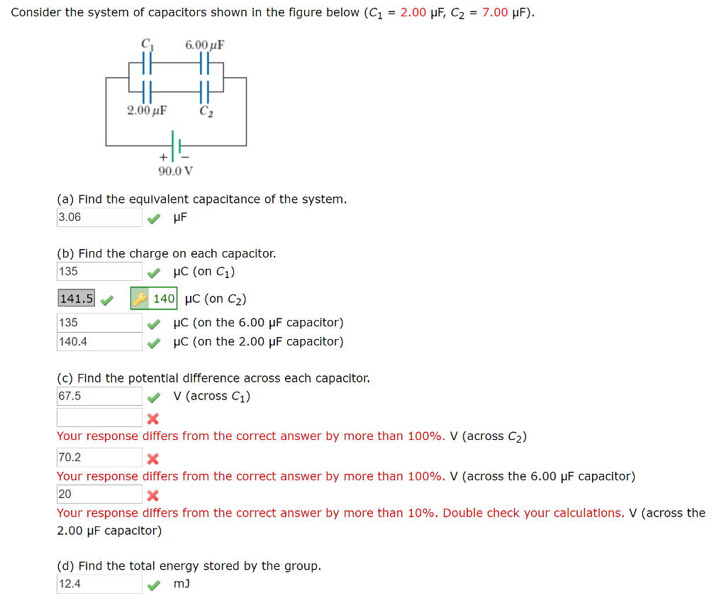
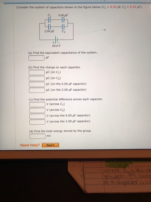
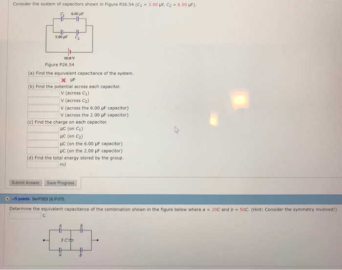
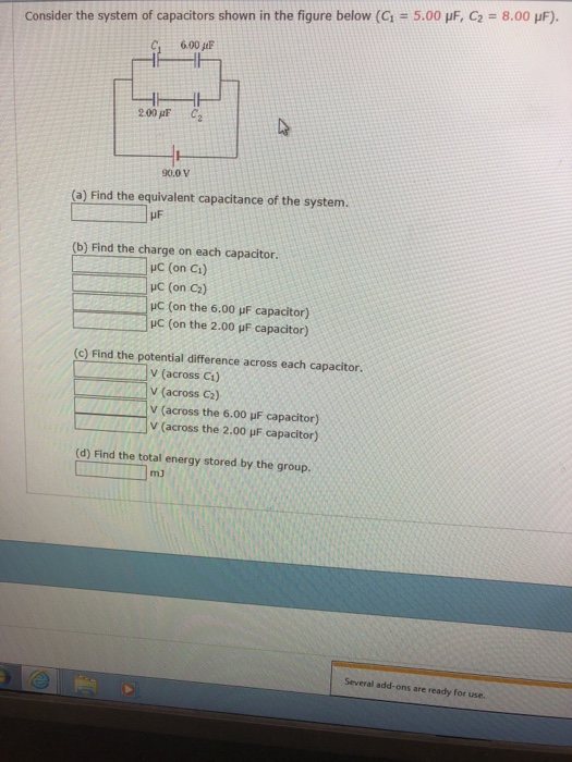
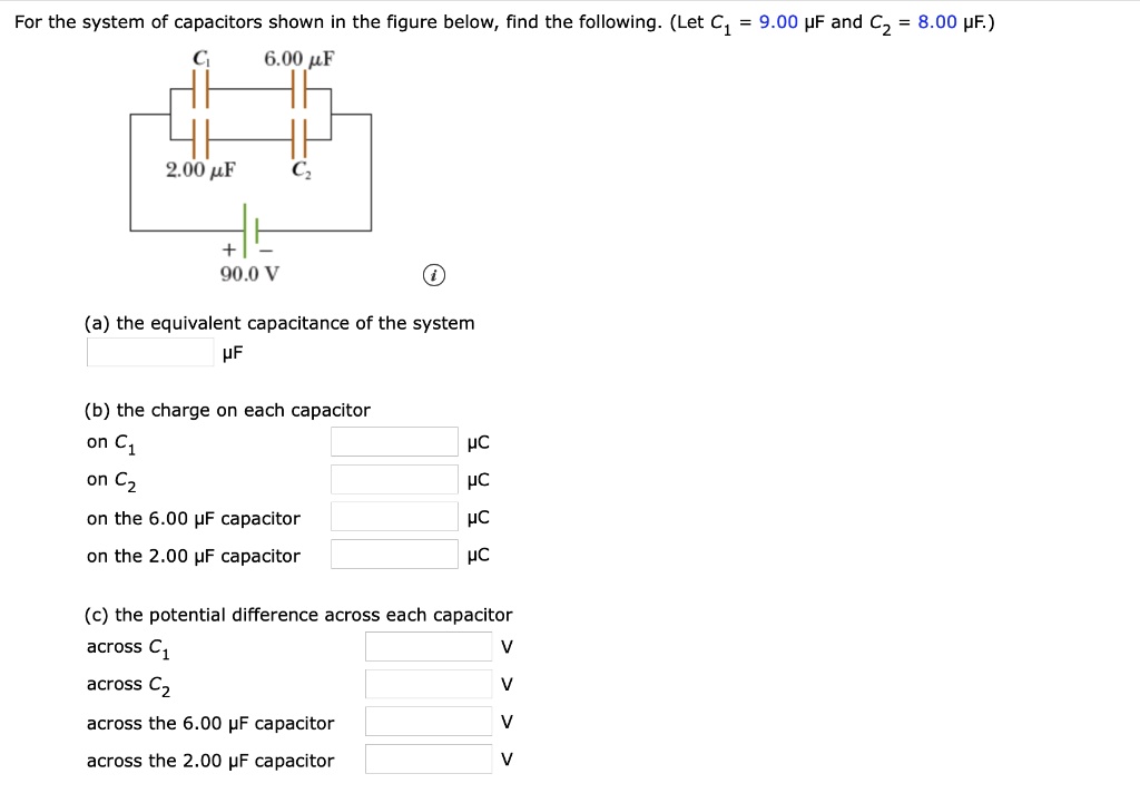
A Find the equivalent capacitance of the system. µF b Find the charge on each capacitor. Physically capacitance is a measure of the capacity of storing electric charge for a given potential difference V.
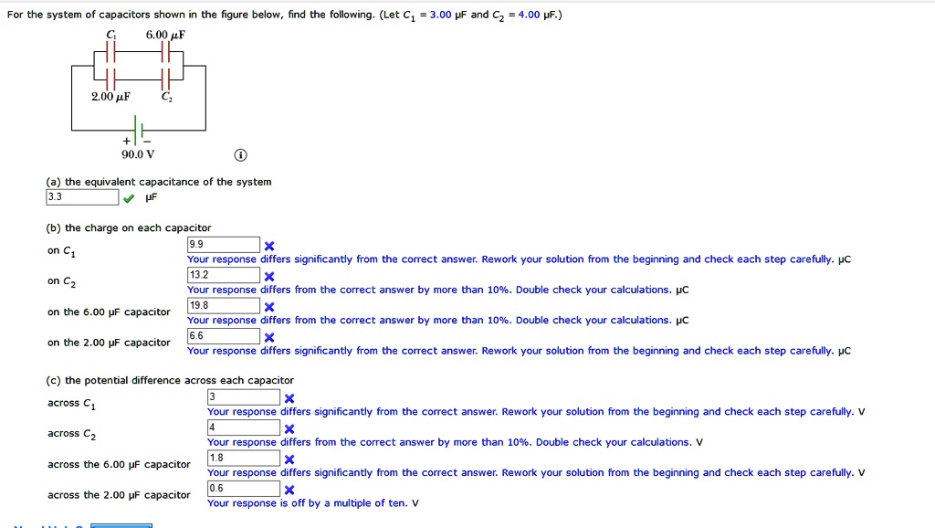
For the system of capacitors shown in the figure find a the equivalent capacitance of the system b the charge on each capacitor and c the potential. Let C1 260 µF and C2 0500 µF a Find the equivalent single capacitance of the two capacitors in series and redraw the diagram called diagram 1 with this equivalent capacitance. Find the potential difference across each capacitor.
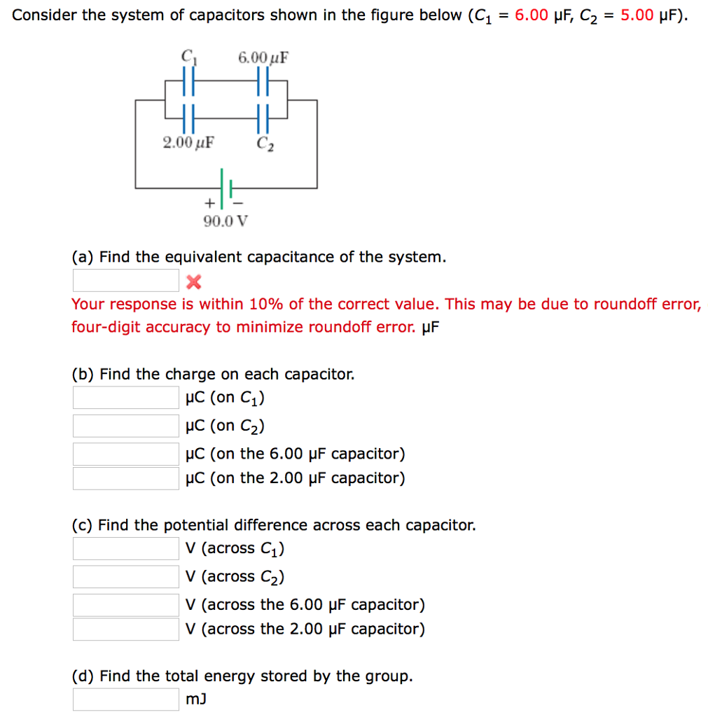
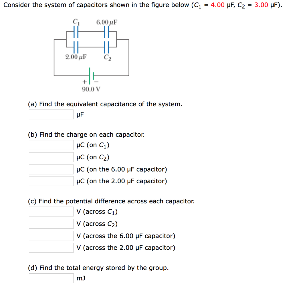
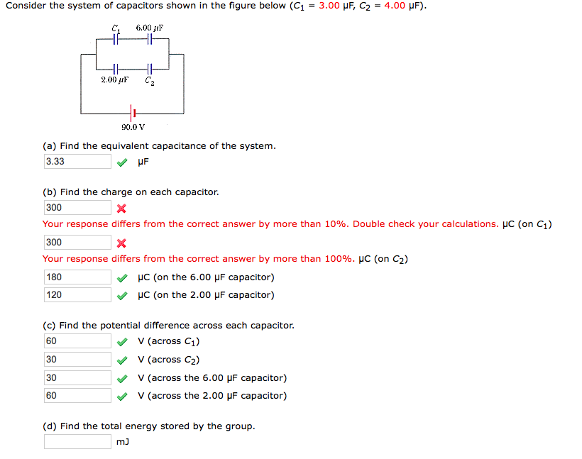
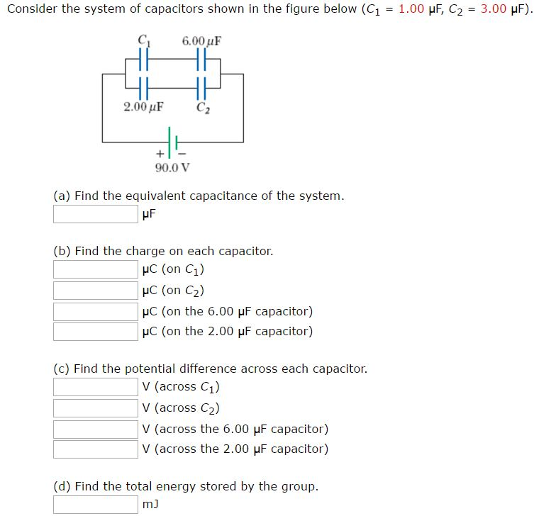
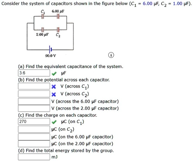
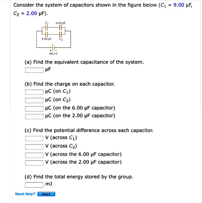
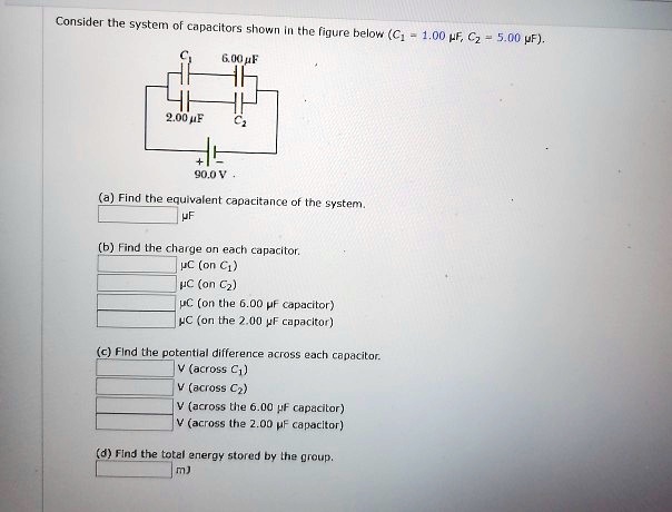
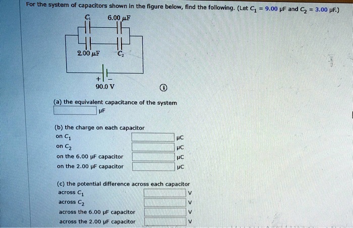
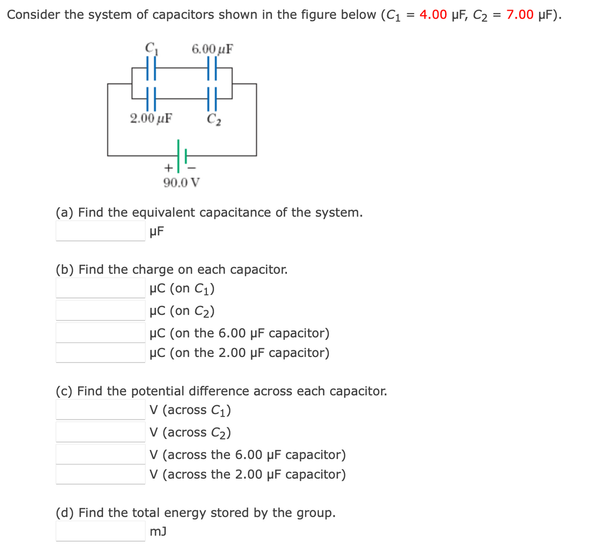
Consider the system of capacitors shown in the figure below C_1 900 mu F C_2 200 mu F. Consider the system ofcapacitors shown in the figure below C1 200 µF C2 900µF. A Find the equivalent capacitance of the systemµF b Find the charge on each capacitorµC on C1µC on C2µC on the 600 µF.
Find the equivalent capacitance of the system. B Find the charge on each capacitor. Consider the system of capacitors shown in the figure below C1 100 HF C2 200 HF 600uF 200 uF C2 900 V a Find the equivalent capacitance of the system.
Consider the system of capacitors shown in the figure below C1 600 microF C2 800 microF. B Calculate the charge on each capa.
Consider the system of capacitors shown in the figure below C_1 900 mu F C_2 200 mu F.
10 t ms -10 Find the currents for the ranges given below. B Find the charge on each capacitor. Consider the system of capacitors shown in the figure below C1 600 microF C2 800 microF. Its terminals are then connected to those of an uncharged 10-pF capacitor. Consider the system of capacitors shown in the figure below C1 500 µF C2 700 µF. 1 pF1012F 1 mF1036F1000µµF. For the system of capacitors shown in the figure find a the equivalent capacitance of the system b the charge on each capacitor and c the potential. How much charge is stored by this system in nC. Consider the system of capacitors shown in the figure below C_1 100 space mu F C_2 800 space mu F C_3 600 space mu F.
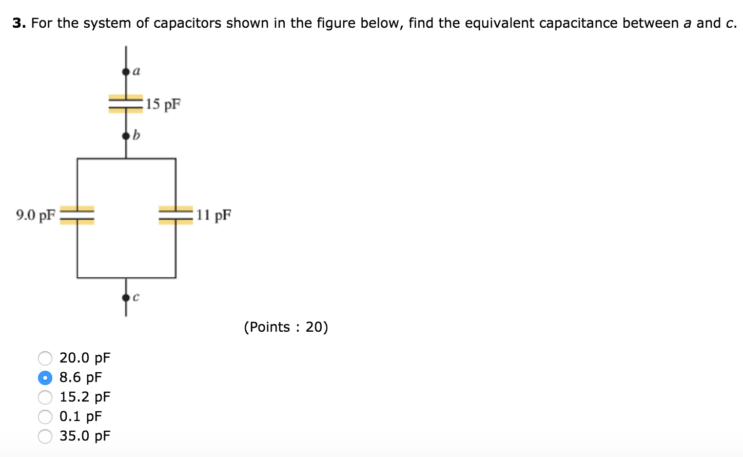
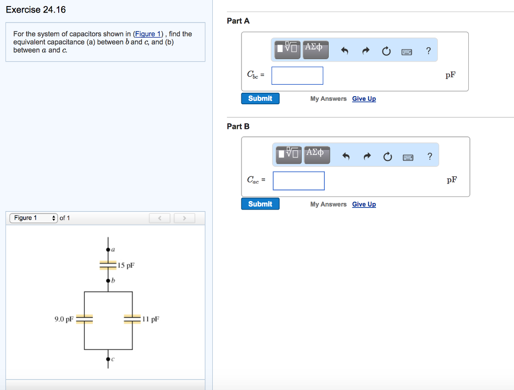
A Find the equivalent capacitance between points a and b. The voltage across a 4-LF capacitor is shown in the given figure. How much charge does the 650 nF capacitor store in nC. µF b Find the charge on each capacitor. For the system of capacitors shown in the the figure below Figure 1 a potential difference of 250 V is maintained across a b. Its terminals are then connected to those of an uncharged 10-pF capacitor. Consider the system of capacitors shown in the figure below C1 100 µF C2 700 µF.














Post a Comment for "Consider The System Of Capacitors Shown In The Figure Below"